Solar Panel Wiring Basics: Series vs Parallel Explained
In solar panel system design, a critical decision is how to wire your panels. This choice directly impacts your system’s voltage and current, which in turn affects everything from component compatibility to performance under various conditions. Understanding the technical fundamentals of series and parallel wiring is essential for ensuring your solar system is safe, efficient, and reliable.
The Basics: Voltage, Current, and Power
Before diving into wiring, it’s important to understand the three key electrical concepts:
- Voltage (V): This measures electrical potential or “pressure.” Think of it as the force that pushes the electric current through a circuit.
- Current (Amps or A): This is the measure of the electric flow rate. It’s the volume of electricity flowing through the circuit.
- Power (Watts or W): The total amount of energy produced. It’s the product of voltage and current (P=V×A).
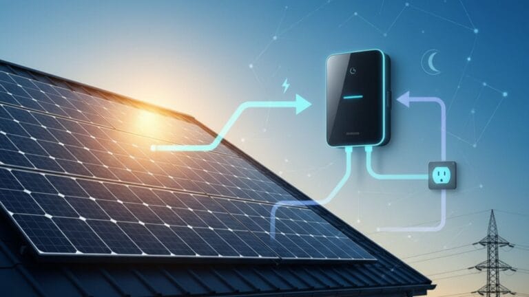
The goal of solar wiring is to configure your panels to produce the ideal voltage and current for your inverter, which then converts the DC power from the panels into the AC power your home uses.
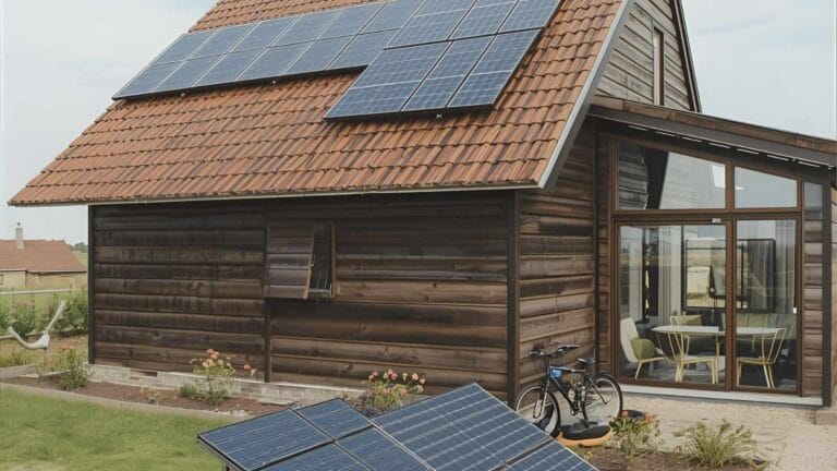
Series Wiring: Boosting Voltage
In a series connection, panels are linked end-to-end, connecting the positive terminal of one panel to the negative terminal of the next.
- What it does: This configuration adds the voltage of each panel while the current remains the same.
- Example: Three 40V, 5A panels wired in series would produce 120V and 5A.
- Pros: This is ideal for systems with a string inverter, which requires a high operating voltage (typically 300-600V) to work efficiently. Higher voltage also allows for thinner, less expensive wiring and reduces energy loss over long cable runs.
- Cons: A series circuit is only as strong as its weakest link. If even a single panel is shaded, covered in debris, or malfunctions, it acts as a bottleneck, reducing the current and power output for the entire string.
Parallel Wiring: Multiplying Current
In a parallel connection, all positive terminals are connected to each other, and all negative terminals are connected to each other.
- What it does: This configuration adds the current of each panel while the voltage remains the same.
- Example: Three 40V, 5A panels wired in parallel would produce 40V and 15A.
- Pros: Parallel wiring is much more tolerant of partial shading. Because each panel operates independently, a shaded panel won’t significantly affect the output of the others. This is a common choice for homes with complex roofs or frequent shading.
- Cons: The higher amperage requires thicker, more expensive wiring to handle the increased current safely. This setup is generally not compatible with standard string inverters.
Expert Recommendation: The Hybrid Approach
For most modern residential solar systems, the best solution is a combination of both. By creating strings of panels in series and then connecting those strings in parallel, you can achieve the ideal balance of voltage and current. This series-parallel configuration is common for larger systems, allowing you to maximize efficiency while mitigating the risks of shading and ensuring compatibility with your inverter.
When to use it: This hybrid approach is best for larger arrays that need both high voltage to meet inverter requirements and high current to handle the system’s size. It offers the benefits of both configurations, providing a robust and flexible solution that maximizes your system’s performance.
Understanding the Fundamentals: Voltage, Current, and Power
Before comparing wiring configurations, it’s essential to understand the key electrical parameters that define a PV system’s performance. These aren’t just technical terms; they are the fundamental building blocks of solar electricity and dictate how your system operates.
The Core Electrical Parameters
- Voltage (V): Think of voltage as the electrical “pressure” that pushes electricity through a circuit. It is a measure of potential energy. A high voltage allows electricity to travel over long distances with minimal energy loss. In solar, each panel has an open-circuit voltage (Voc), which is the maximum voltage it can produce without a load.
- Current (I): This is the flow rate of the electrical charge, or the “volume” of electricity flowing through the circuit. It’s measured in amperes. A panel’s short-circuit current (Isc) is the maximum current it can produce when its terminals are shorted.
- Power (P): Power is the rate at which energy is produced. It’s the product of voltage and current (P=V×I). A panel’s power rating, measured in watts, is the most important metric for determining how much energy it can generate.
Standard Test Conditions (STC) and the Maximum Power Point (MPP)
To allow for a fair comparison between different solar panels, manufacturers rate them under Standard Test Conditions (STC). These are a set of controlled laboratory conditions: 1000 W/m² of solar irradiance, an air mass of 1.5, and a cell temperature of 25°C.
Under these conditions, a panel’s performance is measured to find its Maximum Power Point (MPP). This is the “sweet spot” where the combination of voltage (Vmp) and current (Imp) results in the highest possible power output. A solar inverter’s job is to continuously track and operate at this MPP to maximize your system’s energy harvest throughout the day.
This video provides a practical demonstration of how to measure the electrical parameters of a solar panel.
Series Wiring: Higher Voltage, Constant Current
When designing a solar array, connecting panels in series is a powerful strategy to boost voltage, making it a cornerstone of modern residential systems. This method links panels in a “daisy chain” fashion, where the positive terminal of one panel connects to the negative terminal of the next.
How Series Wiring Works
In a series circuit, the total voltage is the sum of the voltages of each panel. The current, however, remains the same throughout the entire circuit.
- Total Voltage = V₁ + V₂ + … + Vn
- Current = I (constant)
For example, if you connect six 40V, 10A panels in series, the total output is a single string with 240V (
6×40V
) and a current of 10A. This high-voltage output is crucial for modern grid-tied systems, as it’s the ideal input for high-efficiency string inverters. Higher voltage also minimizes energy loss over long cable runs, a benefit for larger properties.
The “Weakest Link” Limitation
The primary drawback of a series configuration is its sensitivity to shading or a single underperforming panel. The entire string’s output is limited by the panel producing the lowest current. This is often called the “Christmas light effect,” where if one bulb goes out, the entire string goes dark. In a solar array, if even one panel is shaded, covered in debris, or malfunctioning, it acts as a bottleneck, reducing the current for all panels in that string. This can significantly reduce the overall power output of your system, which is why a series configuration is only recommended for homes with minimal to no shading.
Parallel Wiring: Constant Voltage, Higher Current
In a parallel solar panel wiring configuration, you connect all the positive terminals together and all the negative terminals together. This setup is fundamentally different from a series connection and offers unique advantages, particularly for systems with partial shading.
How Parallel Wiring Works
In a parallel circuit, the voltage remains constant across all panels, while the current from each panel adds up.
- Total Current = I₁ + I₂ + … + In
- Voltage = V (constant)
For example, if you connect four 12V, 8A panels in parallel, the total output is a single circuit with a voltage of 12V and a current of 32A.
4×8A
This configuration is ideal for low-voltage applications like off-grid systems with low-voltage batteries (e.g., 12V or 24V) and is the standard for systems using microinverters.
The “Independent” Advantage
The main benefit of parallel wiring is that each panel operates independently. If one panel is shaded, its output will be reduced, but it will not significantly affect the performance of the other panels in the circuit. This makes parallel wiring an excellent choice for homes with complex roofs or those with trees or other obstructions that cause intermittent shading throughout the day. This setup ensures that your system continues to produce as much power as possible from all the unshaded panels.
The primary limitation of parallel wiring is the high current. Higher amperage requires thicker, more expensive conductors and fuses to handle the increased electrical flow safely. This can lead to higher material costs and is not an efficient solution for long cable runs, as it can result in significant energy loss.
Combined Series-Parallel Configuration
For larger solar arrays, neither a purely series nor a purely parallel configuration is ideal. Instead, a hybrid approach combining both methods offers the best of both worlds, balancing the need for high voltage with manageable current. This series-parallel wiring is the standard for most medium to large-scale residential and commercial systems.
How the Hybrid System Works
This configuration starts by wiring groups of panels in series to build up the necessary voltage for the inverter. Then, these strings are connected to each other in parallel to increase the total current.
For example, you could wire two separate strings of four panels in series. Each string would have a high voltage output. You would then connect those two strings to each other in parallel. This doubles the total current while keeping the voltage within the safe operating range of the inverter. This method ensures that even if one string is partially shaded, the other string will continue to produce power independently.
The Balancing Act: Sizing and Safety
Designing a series-parallel system requires careful planning and precision.
- String Balancing: It is critical to ensure that each series string has a similar number of panels and a similar voltage to avoid one string “overpowering” another. This ensures that the system works efficiently.
- Combiner Boxes: A combiner box is used to consolidate multiple parallel strings of panels into a single main circuit, which is then connected to the inverter. Combiner boxes are essential for safety as they contain fuses for each string, protecting the system from overcurrent and short circuits.
- String Sizing Tools: Experts and installers rely on specialized string sizing software to optimize these configurations. These tools, often provided by inverter manufacturers, consider the electrical characteristics of both the panels and the inverter, as well as environmental factors, to design a system that maximizes performance and complies with the National Electrical Code (NEC).
By carefully balancing these elements, a series-parallel configuration provides a robust, flexible, and highly efficient solution for maximizing the energy output of your solar array.
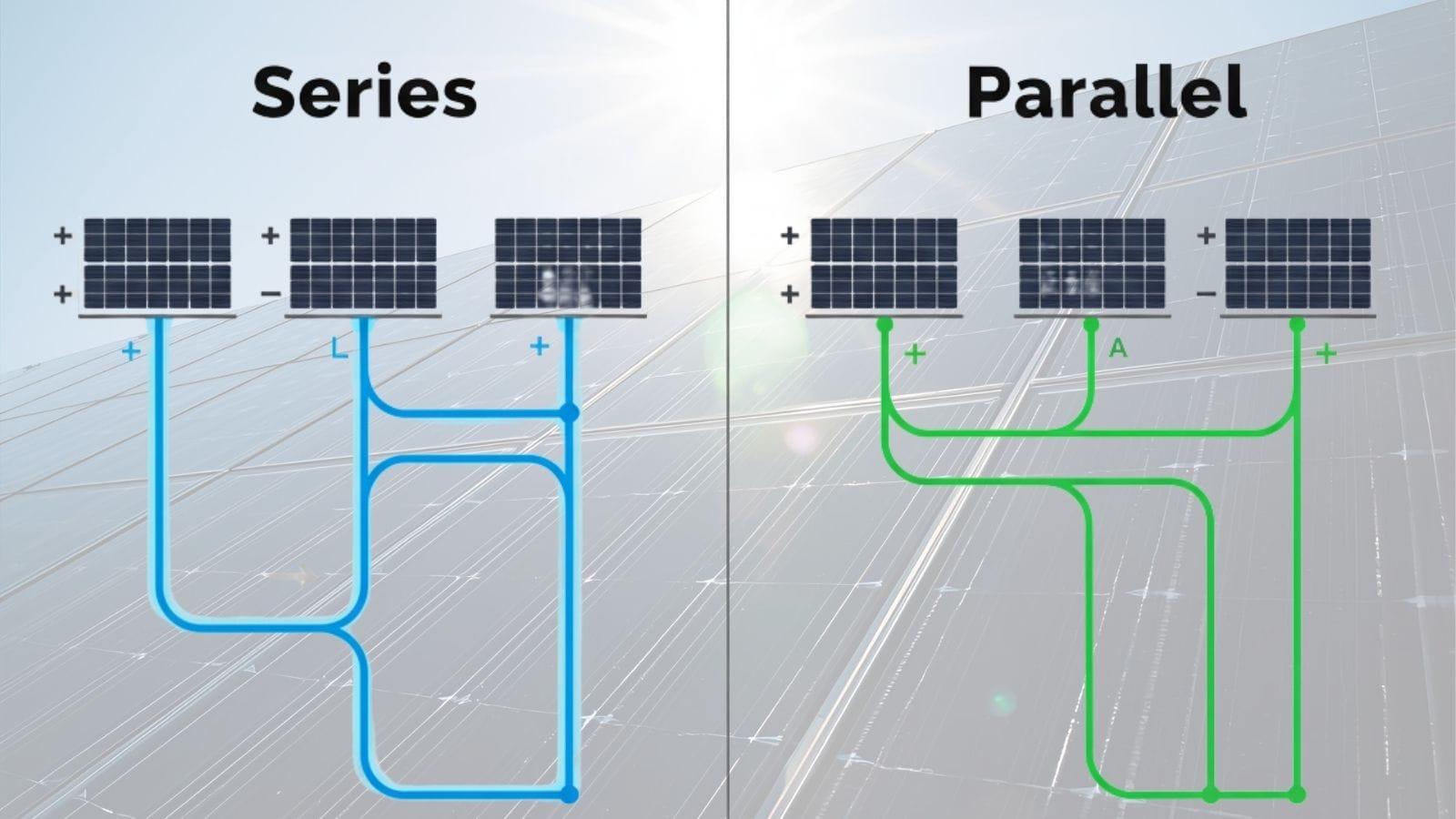
Key Factors to Consider When Choosing a Wiring Method
Choosing a solar panel wiring configuration is a critical decision that impacts your system’s performance, safety, and long-term reliability. The choice between series, parallel, or a combination of both depends on several key technical and practical factors, and there’s no single “best” option for every installation.
1. Inverter and System Voltage Requirements
The most important factor to consider is your inverter’s specifications. String inverters, which are common in residential grid-tied systems, require a high input voltage (typically in the 300–600V range) to operate efficiently. This makes series wiring the natural choice for these systems. In contrast, off-grid systems that charge low-voltage battery banks (12V, 24V, or 48V) often necessitate parallel wiring or the use of a specialized charge controller to prevent overvoltage. It’s crucial to check your inverter’s maximum voltage and current ratings; exceeding these limits can permanently damage the equipment.
2. Shading and Installation Scale
Shading is the enemy of solar power, and your wiring choice can help mitigate its effects.
- Series wiring, while efficient for high voltage, is highly susceptible to the “weakest link” effect. If even a small portion of one panel is shaded, the current for the entire string can drop significantly, reducing the output of all panels in that string. This configuration is best for unshaded roofs.
- Parallel wiring, on the other hand, is far more resilient to shading. Since each panel operates independently, a shaded panel’s underperformance won’t affect the other panels, making it a good choice for roofs with complex shapes or intermittent shading. For larger systems, a hybrid series-parallel approach offers the best of both worlds, creating strings of panels in series to meet voltage requirements and then wiring those strings in parallel to increase current and improve shade tolerance.
3. Electrical and Compliance Considerations
Finally, all wiring decisions must comply with the National Electrical Code (NEC) Article 690, which governs photovoltaic installations. A professional installer ensures that all wiring meets the strict ampacity and overcurrent protection requirements outlined in the code. A professional also handles the complex utility interconnection paperwork, which is often a major hurdle for DIY installers.
This video provides an expert guide on wiring solar panels for an RV or van.
Common Misconceptions and Mistakes in Wiring Design
Mistakes in solar panel wiring can lead to a host of problems, from a simple loss of efficiency to major safety hazards. It’s crucial for homeowners to understand these common misconceptions, as a poorly wired system can compromise your entire investment.
Myth: “Series is always better for efficiency.”
Fact: While series wiring creates the high voltage needed for a string inverter, it suffers from a critical drawback: shading intolerance. A series circuit is like a string of old Christmas lights—if one bulb (or in this case, a single panel) is shaded, dirty, or damaged, it acts as a bottleneck, reducing the current and power output for the entire string. This can significantly reduce your system’s output and is a major reason why professional installers carefully plan panel placement.
Myth: “Parallel wiring avoids all shading problems.”
Fact: Parallel wiring is much more resilient to shading than a series configuration, but it does not completely eliminate the issue. The voltage remains constant, but the current still drops from the shaded panel. The real solution for roofs with significant shading is to use module-level power electronics (MLPEs), such as microinverters or power optimizers. These devices are installed on each individual panel, allowing each one to operate at its maximum power point independently. A shaded panel’s performance will not affect the output of the unshaded panels in the array.
Critical Wiring Mistakes and Their Consequences
Undersizing Conductors: When panels are wired in parallel, the current adds up, which requires thicker wiring to handle the increased electrical flow. Using undersized conductors can lead to overheating, voltage drops, and fire hazards due to excessive heat generation. The National Electrical Code (NEC) specifies strict requirements for wire gauge to ensure safety and prevent these issues. Professional installers are trained to calculate the correct wire size for every run, ensuring your system is safe and compliant.
Ignoring Inverter Input Limits: Every inverter has a maximum voltage and current rating. Exceeding these limits by wiring too many panels in series can cause overvoltage, which can damage the inverter and void its warranty. In the worst-case scenario, it can create a fire risk. Professional installers use specialized string sizing software to ensure the array’s electrical output is perfectly matched to the inverter’s specifications, taking into account temperature variations that affect voltage.
How to Wire Panels Safely: Best Practices
When it comes to solar panel wiring, cutting corners isn’t an option. Proper wiring practices are the backbone of a safe and reliable solar system. They ensure long-term energy yield and protect your investment by preventing common but dangerous failures.
The Foundations of Safe Solar Wiring
The solar industry has established standards to mitigate risk, and adhering to them is non-negotiable. A professional installer ensures every wire and connection meets these critical principles.
- UV-Resistant, Outdoor-Rated PV Wire: Solar wiring is exposed to harsh outdoor conditions for decades. Unlike standard electrical wire, a proper PV wire (such as USE-2 or PV wire) has a tough, UV-resistant jacket designed to withstand extreme temperatures, moisture, and sunlight without cracking or degrading.
- MC4 Connectors: The modern standard for panel-to-panel connections is the MC4 connector. These connectors are designed to be weatherproof with an IP67 rating, ensuring a tight seal against dust and water. Their locking mechanism prevents accidental disconnections, which can lead to dangerous electrical arcing.
- Grounding and Bonding: Grounding is the process of connecting your system to the earth to safely dissipate excess electricity from lightning strikes or surges. Bonding ensures all metal components, like panel frames and racking, are electrically connected to create a continuous path to ground. This prevents dangerous voltage differences between components, eliminating the risk of electrical shock.
NEC Compliance: The Rulebook for Safety
The National Electrical Code (NEC) is the ultimate authority on electrical safety in the U.S. For solar, NEC Article 690 outlines specific requirements that must be followed.
- Overcurrent Protection Devices (OCPDs): In a parallel array, a fault on one string can draw current from other strings, creating a dangerous overcurrent that can damage wiring and cause a fire. OCPDs, like fuses in a combiner box, are a crucial safety feature that automatically shut off power to a faulted string, preventing further damage.
- Rapid Shutdown Systems: In the event of an emergency, firefighters need to know that your rooftop system is de-energized. Rapid shutdown systems, per NEC 690.12, quickly reduce the voltage of conductors to a safe level, providing first responders with peace of mind.
- Labeling and Disconnects: All conductors and equipment must be clearly labeled to prevent confusion and aid in maintenance and emergency response. DC disconnects are also required at the inverter and array to allow the system to be safely shut down for servicing.
This video on explains these essential safety concepts that every solar professional needs to understand.
Choosing the Right Configuration
Choosing the right wiring for your solar panels is a pivotal decision that impacts your entire system’s performance, safety, and longevity. While the concepts of series and parallel wiring seem straightforward, their application is nuanced and directly tied to the specific characteristics of your home and chosen equipment.
The Bottom Line: When to Go Pro
For most homeowners considering a grid-tied system, the combination of technical complexity and regulatory requirements makes DIY a high-risk gamble. The decision to hire a professional is not about avoiding physical labor; it’s about investing in expertise that ensures your system is safe, efficient, and compliant. A certified solar installer provides:
- Technical Precision: They use advanced string sizing software to match the voltage and current of your solar array to your inverter’s specific limits. This prevents overvoltage that could damage equipment and void warranties.
- NEC Compliance: They ensure all wiring, grounding, and safety devices (like rapid shutdown systems) are installed in strict accordance with the National Electrical Code (NEC). This is a non-negotiable requirement for passing inspections and protecting your home from electrical hazards.
- Optimal Performance: They design the array to handle your specific environmental conditions, using microinverters or power optimizers in shaded areas to ensure that one underperforming panel doesn’t compromise the entire system’s output.
The Safer, Smarter Choice
While a basic, small-scale, off-grid system for a cabin or RV might be a feasible DIY project, a full-scale residential installation is far too complex for anyone without a professional background in electrical work. The peace of mind that comes from a properly wired, code-compliant, and fully warranted system is priceless. When you work with a certified installer, you’re not just buying solar panels; you’re buying a long-term, reliable energy solution that will serve your home for decades to come.
Choosing between series and parallel wiring doesn’t just affect technical performance — it can also impact system costs and long-term returns. For a deeper look into cost analysis, check out our guide on calculating solar panel payback periods.
Reference: National Electrical Code (NEC) Article 690

Solar Energy Enthusiast & Renewable Energy Researcher
Vural’s journey into solar energy began four years ago, driven by frequent power outages and high electricity bills at his own home. He has since gained hands-on experience with both personal and commercial solar projects. At solarpanelresource.com, Vural shares his real-world insights and in-depth research to guide homeowners and business owners on their own path to energy independence.